repl.it linkrepl.it link (duplicated)Individual Project (iP):
Team Project (tP):
Week 10 [Fri, Oct 16th] - Topics
Detailed Table of Contents
- [W10.1] Sequence Diagrams: Basics
- [W10.1a] Design → Modelling → Modelling Behaviors Sequence diagrams - basic
- [W10.2] Sequence Diagrams: Intermediate-Level
- [W10.3] Design Patterns
Introduction
-
[W10.3a] Design → Design Patterns → Introduction → What
-
[W10.3b] Design → Design Patterns → Introduction → Format
Singleton pattern
-
[W10.3c] Design → Design Patterns → Singleton → What
-
[W10.3d] Design → Design Patterns → Singleton → Implementation
-
[W10.3e] Design → Design Patterns → Singleton → Evaluation
Facade pattern
- [W10.3f] Design → Design Patterns → Facade Pattern → What
- [W10.4] Testing: Test Coverage
Guidance for the item(s) below:
Good news: this will the the last installment of UML notations.
Bad news: we are going to cover an entire new diagram type in one go (reason: to give you more time to use them in project documentation).
Design → Modelling → Modelling Behaviors Sequence diagrams - basic
Can draw basic sequence diagrams
UML Sequence Diagrams → Introduction UML/SequenceDiagrams
UML Sequence Diagrams → Basic Notation UML/SD/Basic
UML Sequence Diagrams → Loops UML/SD/Loops UML Sequence Diagrams → Object Creation UML/SD/Creation
UML Sequence Diagrams → Minimal Notation UML/SD/Minimal
Exercises
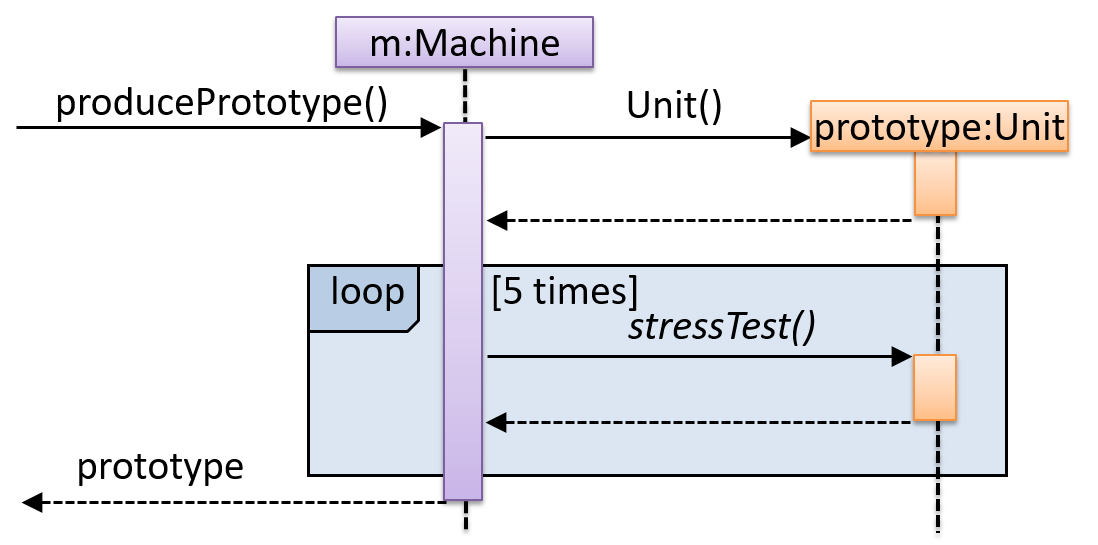
Explain Sequence Diagram about Machine
Explain in your own words the interactions illustrated by this Sequence Diagram:
Draw a Sequence Diagram for the code (PersonList, Person, Tag)
Consider the code below:
class Person {
    Tag tag;
    String name;

    Person(String personName, String tagName) {
        name = personName;
        tag = new Tag(tagName);
    }
}
class Tag {
    Tag(String value) {
        // ...
    }
}

class PersonList {
    void addPerson(Person p) {
        // ...
    }
}
Draw a sequence diagram to illustrate the object interactions that happen in the code snippet below:
PersonList personList = new PersonList();
while (hasRoom) {
    Person p = new Person("Adam", "friend");
    personList.addPerson(p);
}
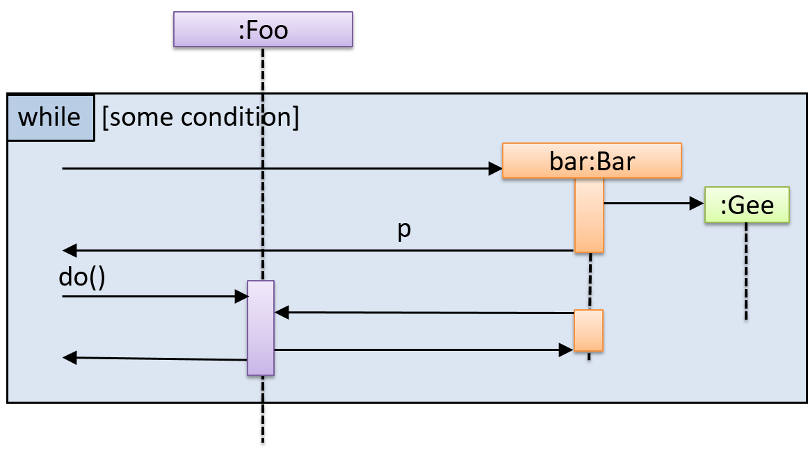
Find notation errors in Sequence Diagram
Find notation mistakes in the sequence diagram below:
Design → Modelling → Modelling Behaviors Sequence diagrams - intermediate
Can draw intermediate-level sequence diagrams
UML Sequence Diagrams → Object Deletion UML/SD/Deletion UML Sequence Diagrams → Self-Invocation UML/SD/Self-Invocation UML Sequence Diagrams → Alternative Paths UML/SD/Alternative UML Sequence Diagrams → Optional Paths UML/SD/Optional
UML Sequence Diagrams → Calls to Static Methods
UML/SD/StaticMethods
Method calls to static (i.e., class-level) methods are received by the class itself, not an instance of that class. You can use <<class>> to show that a participant is the class itself.
In this example, m calls the static method Person.getMaxAge() and also the setAge() method of a Person object p.
Here is the Person class, for reference:
Exercises
What’s going on here?
What’s going on here?
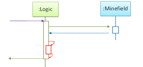
- a.
Logicobject is executing a parallel thread. - b.
Logicobject is executing a loop. - c.
Logicobject is creating anotherLogicinstance. - d. One of
Logicobject’s methods is calling another of its methods. - e.
Minefieldobject is calling a method ofLogic.
(d)
Explain Sequence Diagram (ParserFactory)
Explain the interactions depicted in this sequence diagram.
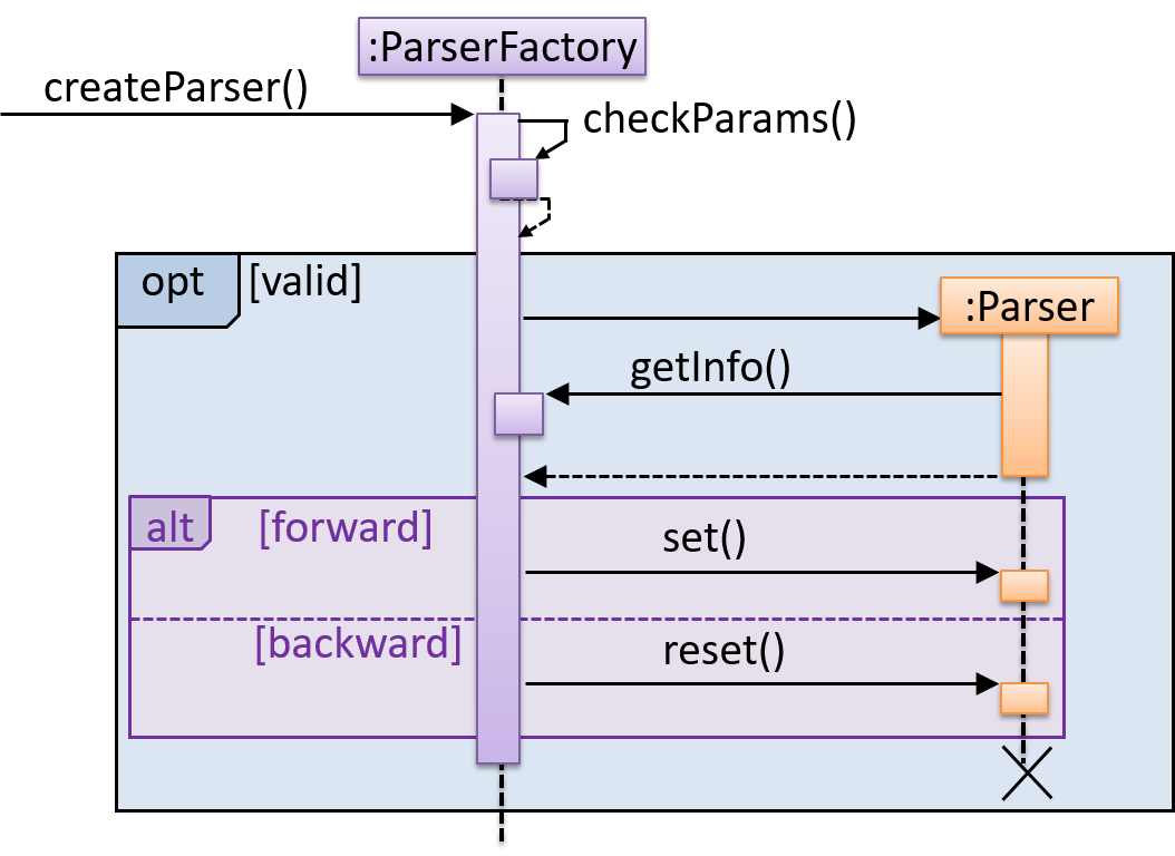
First, the createParser() method of an existing ParserFactory object is called. Then, ...
Draw Sequence Diagram for printing a quote
Draw a sequence diagram to represent this code snippet.
if (isFirstPage) {
    new Quote().print();
}
The Quote class:
class Quote {

    String q;

    Quote() {
        q = generate();
    }

    String generate() {
        // ...
    }

    void print() {
        System.out.println(q);
    }

}
- Show
new Quote().print();as two method calls. - As the created Quote object is not assigned to a variable, it can be considered as 'deleted' soon after its
print()method is called.
Tools → UML → Sequence Diagrams → Parallel paths
Can interpret sequence diagrams with parallel paths
UML uses par frames to indicate parallel paths.
Notation:
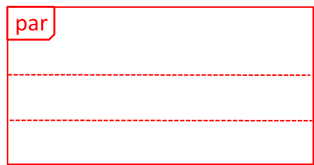
Logic is calling methods CloudServer#poll() and LocalServer#poll() in parallel.
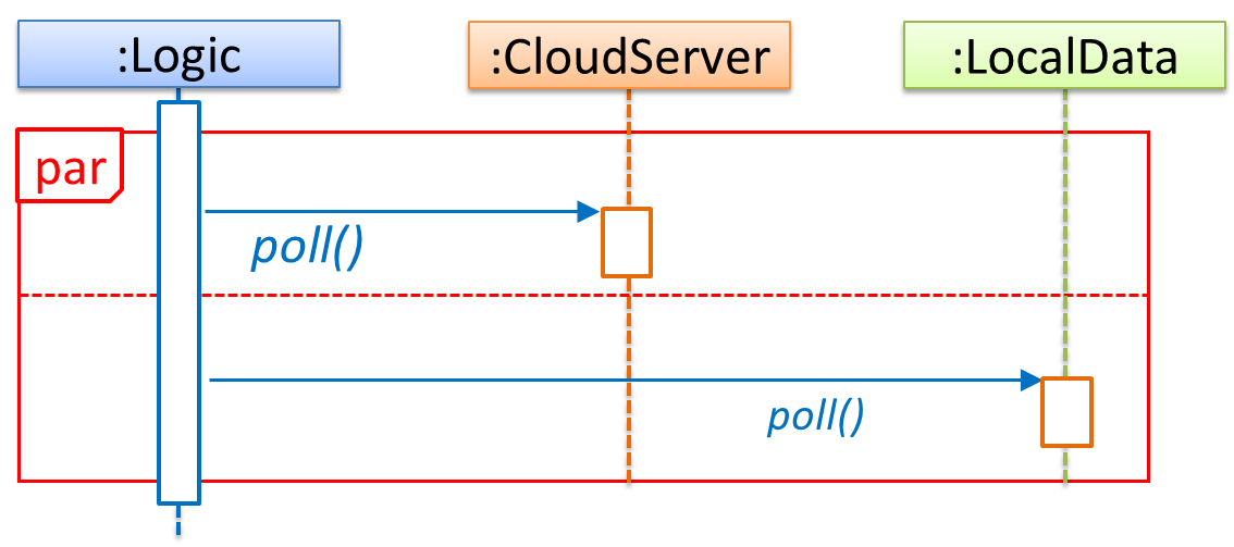
If you show parallel paths in a sequence diagram, the corresponding Java implementation is likely to be multi-threaded because a normal Java program cannot do multiple things at the same time.
Tools → UML → Sequence Diagrams → Reference frames
Can interpret sequence diagrams with reference frames
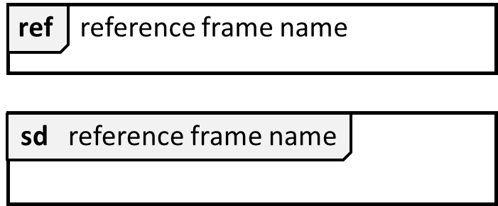
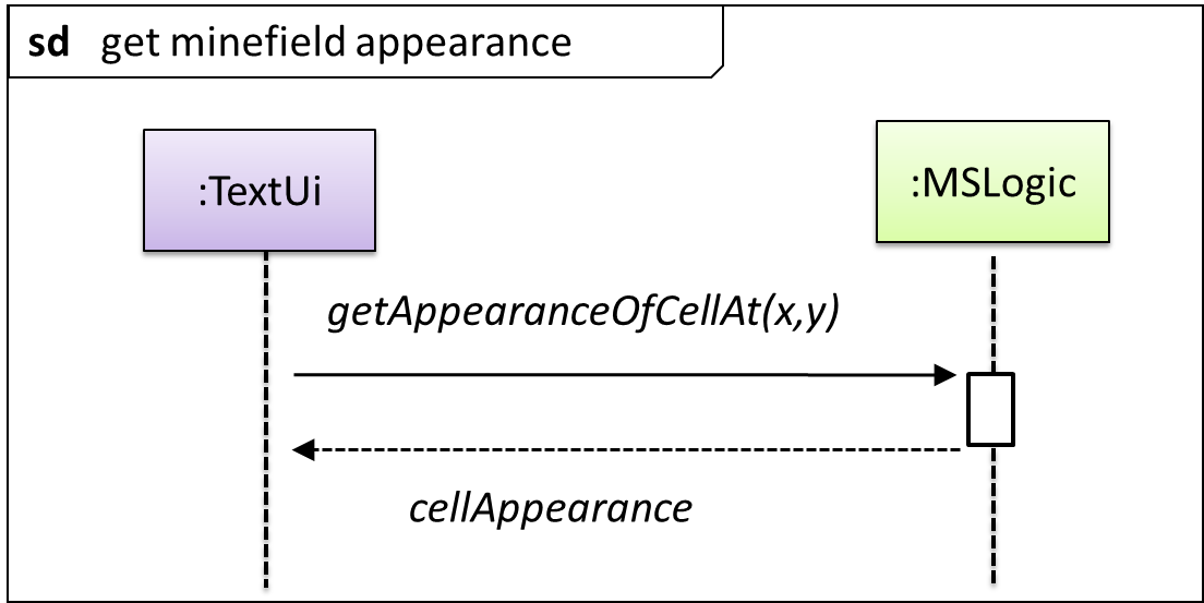
UML uses ref frame to allow a segment of the interaction to be omitted and shown as a separate sequence diagram. Reference frames help you to break complicated sequence diagrams into multiple parts or simply to omit details you are not interested in showing.
Notation:
The details of the get minefield appearance interactions have been omitted from the diagram.
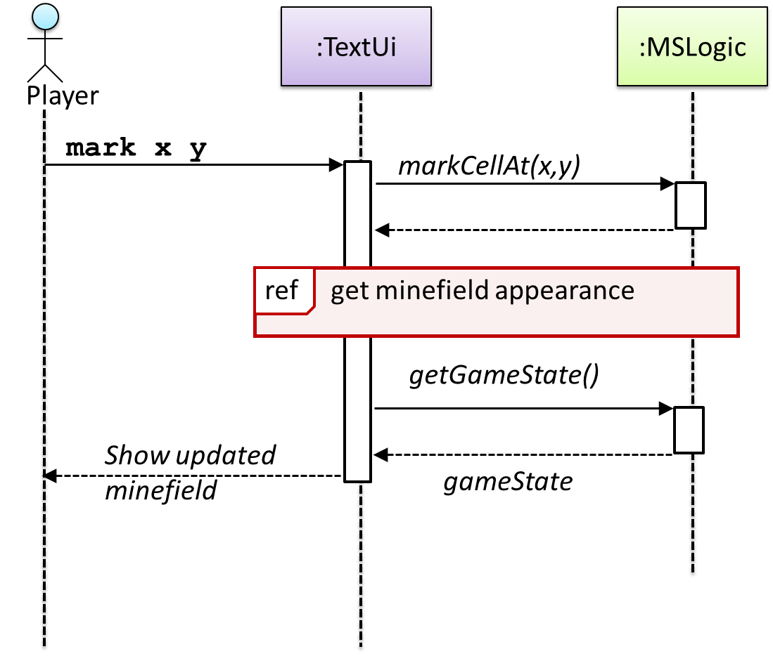
Those details are shown in a separate sequence diagram given below.
Follow up notes for the item(s) above:
After you have learned how to interpret sequence diagrams, you can watch this:
Guidance for the item(s) below:
Previously, you learned:
- Three basic design quality aspects: abstraction, coupling, cohesion
- Some design principles that aims to improve those aspects (e.g., Single Responsibility Principle). There are many more principles but we covered only two (to reduce workload) just to give you a taste only.
This week, we cover design patterns, a concept that builds upon the above. Again, we limit to only two of them, for similar reasons.
Introduction
Guidance for the item(s) below:
First, let's learn what design patterns are, in general.
Design → Design Patterns → Introduction → What
Can explain design patterns
Design pattern: An elegant reusable solution to a commonly recurring problem within a given context in software design.
In software development, there are certain problems that recur in a certain context.
Some examples of recurring design problems:
| Design Context | Recurring Problem |
|---|---|
| Assembling a system that makes use of other existing systems implemented using different technologies | What is the best architecture? |
| UI needs to be updated when the data in the application backend changes | How to initiate an update to the UI when data changes without coupling the backend to the UI? |
After repeated attempts at solving such problems, better solutions are discovered and refined over time. These solutions are known as design patterns, a term popularized by the seminal book Design Patterns: Elements of Reusable Object-Oriented Software by the so-called "Gang of Four" (GoF) written by Eric Gamma, Richard Helm, Ralph Johnson, and John Vlissides.
Exercises
Definition of design patterns
Which one of these describes the ‘software design patterns’ concept best?
(b)
Design → Design Patterns → Introduction → Format
Can explain design patterns format
The common format to describe a pattern consists of the following components:
- Context: The situation or scenario where the design problem is encountered.
- Problem: The main difficulty to be resolved.
- Solution: The core of the solution. It is important to note that the solution presented only includes the most general details, which may need further refinement for a specific context.
- Anti-patterns (optional): Commonly used solutions, which are usually incorrect and/or inferior to the Design Pattern.
- Consequences (optional): Identifying the pros and cons of applying the pattern.
- Other useful information (optional): Code examples, known uses, other related patterns, etc.
Exercises
Anti-patterns required?
When we describe a pattern, we must also specify anti-patterns.
False.
Explanation: Anti-patterns are related to patterns, but they are not a ‘must have’ component of a pattern description.
Guidance for the item(s) below:
Now that you know what design pattern is, let's learn a few example design patterns.
Singleton pattern
Design → Design Patterns → Singleton → What
Can explain the Singleton design pattern
Context
Certain classes should have no more than just one instance (e.g. the main controller class of the system). These single instances are commonly known as singletons.
Problem
A normal class can be instantiated multiple times by invoking the constructor.
Solution
Make the constructor of the singleton class private, because a public constructor will allow others to instantiate the class at will. Provide a public class-level method to access the single instance.
Example:
Exercises
Statements about the Singleton pattern
You use the Singleton pattern when
(c)
Design → Design Patterns → Singleton → Implementation
Can apply the Singleton design pattern
Here is the typical implementation of how the Singleton pattern is applied to a class:
class Logic {
    private static Logic theOne = null;

    private Logic() {
        ...
    }

    public static Logic getInstance() {
        if (theOne == null) {
            theOne = new Logic();
        }
        return theOne;
    }
}
Notes:
- The constructor is
private, which prevents instantiation from outside the class. - The single instance of the singleton class is maintained by a
privateclass-level variable. - Access to this object is provided by a
publicclass-level operationgetInstance()which instantiates a single copy of the singleton class when it is executed for the first time. Subsequent calls to this operation return the single instance of the class.
If Logic was not a Singleton class, an object is created like this:
Logic m = new Logic();
But now, the Logic object needs to be accessed like this:
Logic m = Logic.getInstance();
Design → Design Patterns → Singleton → Evaluation
Can decide when to apply Singleton design pattern
Pros:
- easy to apply
- effective in achieving its goal with minimal extra work
- provides an easy way to access the singleton object from anywhere in the code base
Cons:
- The singleton object acts like a global variable that increases coupling across the code base.
- In testing, it is difficult to replace Singleton objects with stubs (static methods cannot be overridden).
- In testing, singleton objects carry data from one test to another even when you want each test to be independent of the others.
Given that there are some significant cons, it is recommended that you apply the Singleton pattern when, in addition to requiring only one instance of a class, there is a risk of creating multiple objects by mistake, and creating such multiple objects has real negative consequences.
Facade pattern
Design → Design Patterns → Facade Pattern → What
Can explain the Facade design pattern
Context
Components need to access functionality deep inside other components.
The UI component of a Library system might want to access functionality of the Book class contained inside the Logic component.
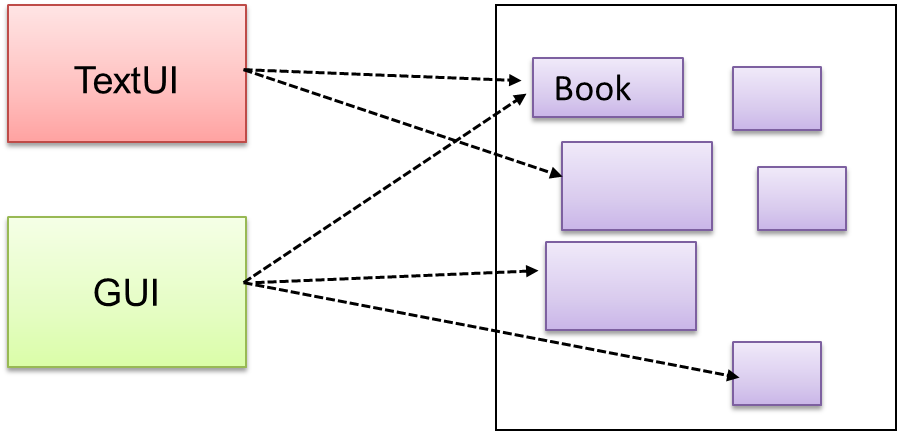
Problem
Access to the component should be allowed without exposing its internal details. e.g. the UI component should access the functionality of the Logic component without knowing that it contains a Book class within it.
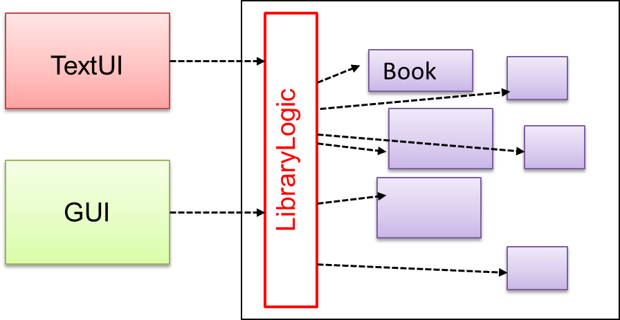
Solution
Include a a French word that means 'front of a building'Façade class that sits between the component internals and users of the component such that all access to the component happens through the Facade class.
The following class diagram applies the Facade pattern to the Library System example. The LibraryLogic class is the Facade class.
Exercises
Is this Facade?
Is the design below likely to use the Facade pattern?
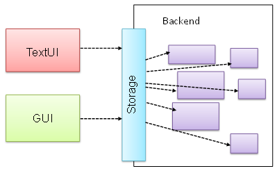
True.
Facade is clearly visible (Storage is the <<Facade>> class).
Follow up notes for the item(s) above:
To learn more design patterns, you can refer to https://se-education.org/se-book/designPatterns/
Guidance for the item(s) below:
Previously, you learned how to write JUnit tests. How do you know which parts of the code is being tested by your tests? That's where test coverage comes in.
Quality Assurance → Testing → Test Coverage → What
Can explain test coverage
Test coverage is a metric used to measure the extent to which testing exercises the code i.e., how much of the code is 'covered' by the tests.
Here are some examples of different coverage criteria:
- Function/method coverage : based on functions executed e.g., testing executed 90 out of 100 functions.
- Statement coverage : based on the number of lines of code executed e.g., testing executed 23k out of 25k LOC.
- Decision/branch coverage : based on the decision points exercised e.g., an
ifstatement evaluated to bothtrueandfalsewith separate test cases during testing is considered 'covered'. - Condition coverage : based on the boolean sub-expressions, each evaluated to both true and false with different test cases. Condition coverage is not the same as the decision coverage.
if(x > 2 && x < 44) is considered one decision point but two conditions.
For 100% branch or decision coverage, two test cases are required:
(x > 2 && x < 44) == true: [e.g.x == 4](x > 2 && x < 44) == false: [e.g.x == 100]
For 100% condition coverage, three test cases are required:
(x > 2) == true,(x < 44) == true: [e.g.x == 4](x < 44) == false: [e.g.x == 100](x > 2) == false: [e.g.x == 0]
- Path coverage measures coverage in terms of possible paths through a given part of the code executed. 100% path coverage means all possible paths have been executed. A commonly used notation for path analysis is called the Control Flow Graph (CFG).
- Entry/exit coverage measures coverage in terms of possible calls to and exits from the operations in the SUT.
Exercises
Highest intensity coverage
Which of these gives us the highest intensity of testing?
(b)
Explanation: 100% path coverage implies all possible execution paths through the SUT have been tested. This is essentially ‘exhaustive testing’. While this is very hard to achieve for a non-trivial SUT, it technically gives us the highest intensity of testing. If all tests pass at 100% path coverage, the SUT code can be considered ‘bug free’. However, note that path coverage does not include paths that are missing from the code altogether because the programmer left them out by mistake.
Guidance for the item(s) below:
Learn how to measure test coverage in your tP. You will be asked to demo that in the coming tutorial.
Quality Assurance → Testing → Test Coverage → How
Can explain how test coverage works
Measuring coverage is often done using coverage analysis tools. Most IDEs have inbuilt support for measuring test coverage, or at least have plugins that can measure test coverage.
Coverage analysis can be useful in improving the quality of testing e.g., if a set of test cases does not achieve 100% branch coverage, more test cases can be added to cover missed branches.
Measuring code coverage in Intellij IDEA